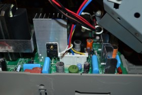
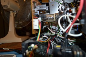
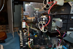
Ian has had some communication with me already, but I decided to make this a post since it's easier to read and come back to than a PM asking him something. Heh. I did some further testing today. I found every pot I could and tweaked it while the monitor was live. I have pictures of the things I adjusted below, click them to see them larger on Imageshack.
The pot RV501 on the A main board turned out to be horizontal center. I can adjust H center digitally in the menus as well, but not size which is the one I need. The screen is far too wide and a bit pin cushioned. Those adjustments don't seem to work either, but vertical position and such do. So strange. Here is a picture of RV501. Look for the black shaft near the yoke wires.

I also adjusted the pot on the neck board, labeled C board, that was surrounded by a black cover. Turns out this was horizontal separation of the color beams. I tweaked it a tad and I could see red and blue on either side of the menu letters. They're supposed to be pure white. I re-tweaked it and I think it's closer calibrated that it was to start with, glad I messed with that. If I can figure out the horizontal issue, the picture quality will be mint. Here's a pic of the neck board, The pot has a white shaft, look below the picture tube neck.

Lastly, I screwed with what I believe is the horizontal size coil. It's a coil with an Allen style screw in the center and it's mounted on the yoke. I adjusted it while the monitor was on and had a source hooked to the composite in and it did nothing when moved. Below is a picture at an angle that shows the coil, look on the yoke and the coils are covered in white tape.

Also, I tested some points and the voltages seemed to be in spec, which didn't surprise me since the monitor will actually work and display a picture. Something internally has caused the horizontal to collapse outward and not be adjustable. I actually don't have a scope to test waveforms and I can only do a limited amount of probing until I get some better clip on test leads, but I guess I could just see if any resistors or diodes have bridged or went open. I can print out the component lists and check them off as I go. Time consuming as all hell, but worth a check I guess. Start on the A board since it pretty well deals with all vertical/horizontal business.


